


Views: 0 Author: Site Editor Publish Time: 2026-06-19 Origin: Site


Capturing sub-micron particles in high-efficiency filtration systems creates an inherent engineering conflict. Forcing air through dense media restricts airflow, which drives up static pressure and increases energy consumption. Facility managers often face the challenge of balancing strict air purity standards with manageable operating costs. Suboptimal filter geometry directly exacerbates this problem. Poor pleat spacing leads to media blinding, uneven dust loading, premature filter failure, and excessive HVAC energy consumption.
The engineering behind modern filtration addresses these specific aerodynamic challenges. Precise pleat geometry optimizes the ratio of media surface area to air velocity. By utilizing advanced manufacturing techniques, a mini pleat HEPA filter solves the resistance problem. This design eliminates bulky mechanical separators, ensuring uniform airflow and reducing the fan horsepower required to maintain critical cleanroom environments.
Geometry Dictates Resistance: Optimal pleat spacing reduces the velocity of air passing through the media, directly lowering initial pressure drop and extending filter life.
Separatorless Innovation: Utilizing hot-melt adhesive beads instead of corrugated aluminum separators prevents media damage, eliminates dead zones, and ensures uniform airflow.
Energy vs. Capital Cost: While mini pleat filters carry a higher initial procurement cost, the reduction in fan energy consumption yields lower long-term operating expenses in continuous-operation environments.
System Integrity: Pairing optimized pleat packs with a gel seal HEPA filter frame eliminates bypass risks, ensuring compliance in critical cleanroom applications.
Airflow resistance, commonly measured as pressure drop, dictates the efficiency of HVAC and cleanroom systems. Every filter introduces a physical barrier to the airstream. The fan must work harder to push air through this barrier, consuming more electrical power. The primary success criteria for high-efficiency filtration involve maximizing particle capture while minimizing this required fan horsepower. Achieving this balance requires precise control over how air interacts with the filter media. When you measure resistance across a filter bank using a magnehelic gauge, you are directly observing the aerodynamic penalty of the filter's physical structure.
In field applications, resistance is not a static number. It changes dynamically as the filter loads with particulate matter. The goal is to start with the lowest possible initial pressure drop and maintain a shallow resistance curve over time. This requires a filter design that utilizes every square inch of media evenly, preventing localized loading that forces the fan to ramp up RPMs to maintain the required air changes per hour (ACH).
Fluid dynamics play a critical role in filter performance. Packing too many pleats into a single frame creates narrow channels. This increases the air velocity between the pleats, causing surface friction and driving up the overall resistance. The air struggles to penetrate the media evenly, leading to turbulent flow and higher energy demands. When pleats are jammed together, the effective open area decreases, forcing the air to accelerate just to get through the frame.
Conversely, utilizing too few pleats reduces the total available media surface area. When the surface area decreases, the same volume of air must pass through the remaining media at a significantly higher velocity. This velocity spike forces particles deeper into the media matrix rapidly, spiking resistance and reducing the overall filtration efficiency. High face velocity through the media also increases the risk of particle blow-through, where captured contaminants are dislodged and pushed downstream.
Physical permeability coefficients of the filter media shift under these localized high-velocity spikes. When air hits specific sections of the media too fast, the pressure drop curve accelerates exponentially. Maintaining a balanced operational velocity across the entire filter face prevents these localized spikes and ensures consistent permeability. Engineers calculate the optimal pleat density by balancing the media area against the cross-sectional open area of the pleat channels.
High air pressure can force poorly spaced pleats to pinch together. This phenomenon is known as V-banding. When pleats collapse against each other, they effectively blind large sections of the media. The air can no longer pass through the pinched areas, restricting the overall airflow. This forces the remaining open media to handle the entire air volume, causing an exponential increase in pressure drop and drastically shortening the filter lifespan.
In systems with variable frequency drives (VFDs), V-banding creates a destructive feedback loop. As the pleats pinch and resistance rises, the VFD ramps up the fan speed to maintain airflow. The increased air pressure pinches the pleats even tighter, further blinding the media and forcing the fan to work even harder until the system reaches its maximum static pressure limit.
Even pleat spacing distributes air uniformly across the entire surface area of the filter. This aerodynamic balance allows particles to load evenly across the media. Uniform loading prevents dust and contaminants from concentrating in high-velocity zones. By avoiding localized concentration, the filter maintains a stable pressure drop over a longer period, preventing premature blinding and reducing the frequency of maintenance replacements.
When you inspect a properly spaced filter at the end of its lifecycle, the dust cake is visually uniform across the entire face. In contrast, a filter with poor spacing will show heavy, dark bands of particulate where the air was forced through narrow channels, while other areas remain relatively clean. This uneven loading indicates that a significant portion of the expensive filter media was completely wasted.
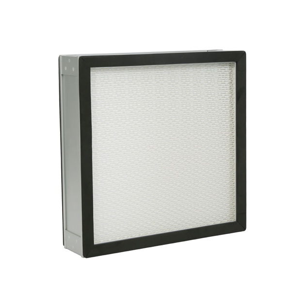
Traditional high-efficiency filters rely on mechanical separation, typically using corrugated aluminum foil to keep pleats apart. While effective at maintaining structure, these metal separators block a portion of the airflow and create dead zones. Modern filtration approaches utilize adhesive-based separation. This transition to a separatorless HEPA filter design maximizes open media area and significantly reduces internal airflow turbulence.
The shift away from aluminum separators also eliminates the risk of the sharp metal edges puncturing the delicate fiberglass media during handling or under heavy air pressure. By removing the metal, manufacturers create a lighter, safer, and more aerodynamically efficient product that performs better in high-velocity applications.
The manufacturing process of a separatorless design relies on continuous beads of hot-melt adhesive. These beads are typically applied on precise two-inch centers along the media. As the adhesive hardens, it maintains rigid, aerodynamic, and uniform spacing over the entire range of air flow operation. This precise application ensures the pleats remain perfectly parallel under varying fan pressures.
The hot-melt adhesive used to separate the pleats creates a seamless structural barrier. It acts as a rigid divider that holds the pleat pack firmly in place without damaging the delicate fiberglass or PTFE media. This seamless integration reduces the chance of air bypassing the filter media, ensuring that all air passes through the filtration matrix as intended.
During production, the adhesive is extruded directly onto the media just before it is folded. The temperature and viscosity of the adhesive are strictly controlled to ensure it bonds securely to the media without bleeding through and blinding the opposite side. This level of manufacturing precision is what gives the final product its structural integrity.
The mini pleat design allows for a much shallower filter depth. A standard configuration can range from two to four inches deep while maintaining or exceeding the surface area of a traditional twelve-inch deep-pleat filter. By eliminating bulky aluminum separators, manufacturers can pack more usable media into a smaller physical footprint.
Even air distribution across this larger usable surface allows particles to load uniformly. When the entire media area is active, no single section bears the brunt of the particulate load. This uniform utilization prevents localized resistance spikes and ensures the filter operates efficiently throughout its intended lifecycle.
The shallow depth also reduces the sheer volume of material required for the frame, further decreasing the weight and environmental footprint of the filter. This compact design is highly advantageous in modern cleanroom architectures where ceiling plenum space is heavily restricted by other mechanical and electrical systems.
Exact spacing technology scales seamlessly to Ultra-Low Penetration Air (ULPA) filtration configurations. ULPA filters utilize significantly denser media structures to capture even smaller particles. Keeping flow resistance low in these dense filters is highly critical. The precision of hot-melt adhesive spacing prevents the dense media from collapsing, ensuring ULPA systems deliver necessary air purity without overwhelming the HVAC fan motors.
Because ULPA media is inherently more restrictive, any flaw in pleat spacing is magnified. The adhesive bead technology provides the exact tolerances required to keep the dense pleats open and functional. Without this technology, achieving ULPA-level filtration in a standard HVAC system would require massive, impractical fan upgrades.
Facility managers and engineers need a clear comparative framework when deciding between legacy and modern filter types. Evaluating filters based on pressure drop, space utilization, and structural integrity provides a direct link between physical features and operational outcomes. This framework guides accurate specification for cleanroom upgrades and new facility construction.
Feature | Deep Pleat (Aluminum Separator) | Mini Pleat (Separatorless) |
|---|---|---|
Typical Depth | 11.5 to 12 inches | 2 to 4 inches |
Initial Pressure Drop | Higher (due to metal blockage) | Lower (optimized aerodynamics) |
Weight | Heavy (metal separators add mass) | Lightweight (adhesive is minimal mass) |
Media Damage Risk | High (sharp aluminum edges) | Low (smooth adhesive beads) |
Airflow Turbulence | Moderate to High | Very Low |
Comparing the initial pressure drop curves reveals significant differences. At identical cubic feet per minute (CFM) ratings, mini pleat designs consistently demonstrate lower initial resistance than deep pleated alternatives. The absence of airflow-blocking metal separators allows air to glide through the pleat pack with minimal friction.
These pressure drop reductions translate directly into measurable energy savings. Lower resistance means fan motors draw fewer kilowatt-hours (kWh) to maintain the required air change rates. Over a standard three-to-five-year filter lifecycle, the cumulative energy savings often offset the initial procurement costs of the advanced filtration units.
To calculate these savings, engineers use the formula: Energy (kWh) = (CFM × Pressure Drop × Hours of Operation) / (Fan Efficiency × Motor Efficiency × 8520). By plugging in the lower pressure drop values of the separatorless design, the reduction in annual energy consumption becomes immediately apparent, justifying the upgrade.
Thinner filter profiles offer major architectural advantages. In facilities utilizing Fan Filter Units (FFUs) or tight ceiling plenums, vertical space is highly valuable. A two-inch or four-inch filter depth allows for more compact ceiling grids and easier integration of secondary facility systems, such as lighting and fire suppression piping.
When retrofitting older facilities, gaining eight inches of vertical clearance in the ceiling plenum can be the difference between a successful upgrade and a costly structural modification. The compact nature of these filters provides architects and mechanical engineers with much-needed flexibility during the design phase.
Eliminating corrugated aluminum separators significantly reduces the overall weight of the filter unit. This weight reduction makes handling, transportation, and installation much safer and easier for maintenance personnel. Additionally, lighter filters exert less structural load on suspended cleanroom ceiling grids, simplifying architectural engineering requirements.
A standard 24x48 inch deep pleat filter can weigh upwards of 40 pounds, requiring two technicians to safely install it overhead. A comparable separatorless filter weighs less than half that amount, allowing a single technician to handle the installation, reducing labor costs and minimizing the risk of workplace injuries.
Buyers must demand specific performance metrics when shortlisting manufacturers. Relying solely on nominal efficiency ratings is insufficient for critical environments. Specifications should mandate precise pleat spacing, specific adhesive application methods, and rigorous factory testing protocols to ensure the delivered product matches the engineered design.
When reviewing submittals, look for detailed construction data. The specification should call out the exact type of hot-melt adhesive, the spacing interval of the beads, and the specific grade of media used. Vague specifications lead to inferior substitutions that will fail under operational stress.
Advanced filter frames utilize non-Newtonian fluid tracks to ensure a perfect seal. A gel seal HEPA filter features a channel filled with a specialized polyurethane or silicone gel. When the knife-edge of the housing presses into this gel, the fluid displaces around the edge, creating a completely airtight barrier that accommodates minor structural shifts.
Combining a low-resistance mini pleat pack with a gel seal is the industry standard for pharmaceutical and semiconductor cleanrooms. This combination achieves zero installation leakage. The low resistance prevents excessive backpressure on the seal, while the gel ensures no untreated air bypasses the filter media, maintaining strict ISO classification standards.
Unlike traditional neoprene gaskets that require massive mechanical compression to seal, the gel track requires minimal force. The knife-edge simply rests in the fluid. This eliminates the risk of warping the filter frame during installation, which is a common cause of bypass leaks in older gasket-seal systems.
Factory testing is non-negotiable for critical filtration systems. Specifications must require individual filter testing according to standards such as EN 1822 or IEST-RP-CC001. These tests verify both the exact pressure drop and the fractional efficiency of each specific unit before it leaves the manufacturing facility.
Buyers should request specific pressure drop versus airflow curves from manufacturers. Nominal ratings often fail to reflect actual performance under specific facility conditions. Analyzing the actual performance curves ensures the selected filters will perform efficiently at the exact CFM required by the facility design.
Specified systems must meet strict cleanroom validation and particle deposition criteria during commissioning. Proper documentation of factory tests and post-installation leak tests guarantees that the cleanroom meets regulatory requirements for operational readiness. Always require the factory test report to be shipped in the box with the corresponding serialized filter.
Switching to or installing modern filtration systems presents practical challenges. Facility teams must update their standard operating procedures to handle new materials and form factors. Addressing these risks proactively prevents costly damage and ensures the filters perform as specified.
The primary risk during implementation is physical damage to the media. Because the media is exposed and highly fragile, any contact with tools, scaffolding, or hands will cause a tear. Training maintenance personnel on the specific handling requirements of these filters is the most critical step in a successful deployment.
The exposed fiberglass or PTFE media in separatorless designs is highly susceptible to puncture. Without metal separators acting as a physical shield, careless handling during installation easily damages the media matrix. Even a microscopic tear compromises the entire filter efficiency.
To mitigate this risk, specify filters with protective faceguards. Facility managers must enforce strict standard operating procedures (SOPs) that require technicians to handle filters exclusively by the outer frame, ensuring hands and tools never touch the delicate media. Faceguards add a minimal amount of resistance but provide massive protection against accidental damage.
Step 1: Unboxing & Visual Inspection: Carefully remove the filter from its packaging. Verify the adhesive bead alignment and check the media for any signs of transit damage before moving it to the installation site.
Step 2: Frame-Only Handling: Force strict adherence to handling the housing unit frame. Technicians must avoid contacting the media pack or the gel sealant tracks to prevent contamination or physical damage.
Step 3: Knife-Edge Alignment: Direct the alignment of the housing knife-edge straight into the center of the gel seal channel. Ensure the insertion is perfectly vertical to prevent scraping the gel out of the track.
Step 4: Controlled Torque Clamping & Leak Testing: Standardize mechanical compression using calibrated tools. Execute post-installation aerosol photometer leak testing to verify zero bypass and confirm the integrity of the seal.
Depth mismatches present a significant risk when replacing legacy filters. Installing a two-inch or four-inch mini pleat into an existing HVAC bank designed for twelve-inch deep pleats can cause air bypass or unstable mounting.
To mitigate this, use engineered adapter frames. Alternatively, specify high-capacity V-bank mini pleat configurations that are explicitly designed to fit securely into standard Air Handling Unit (AHU) tracks without requiring extensive hardware modifications. These V-bank designs provide the benefits of separatorless media while matching the physical dimensions of legacy hardware.
Hot-melt adhesives and specific filter media can degrade in high-humidity or high-temperature environments. Excessive moisture can weaken the structural integrity of the pleat spacing, leading to collapse and media blinding.
Verify the operating temperature limits of the adhesive used by the manufacturer. If the facility experiences high humidity, select water-resistant media grades and ensure the adhesive formulation is rated for the specific environmental conditions. Standard hot-melt adhesives typically fail above 150 degrees Fahrenheit, so high-temperature applications require specialized silicone or ceramic spacing materials.
Precise pleat spacing is the primary mechanism for controlling airflow resistance. By preventing media blinding and ensuring uniform particle loading, advanced pleat geometry significantly reduces HVAC energy costs. The structural integrity provided by hot-melt adhesive ensures consistent performance across the filter's lifespan.
Facility engineers should specify separatorless mini pleats for new cleanroom builds, high-energy-cost facilities, and space-constrained plenums. Pairing these optimized pleat packs with gel seals provides the ultimate safeguard for critical environments, ensuring zero bypass leakage and strict regulatory compliance.
Audit your current HVAC pressure drop data to identify inefficiencies in your existing filter banks.
Calculate the potential fan energy savings achievable by upgrading to low-resistance filtration.
Request detailed technical data sheets and actual airflow resistance curves from qualified filter manufacturers.
Update your facility's standard operating procedures to include strict frame-only handling protocols for new filter installations.
A: Standard deep pleat filters use corrugated aluminum separators and are typically 12 inches deep. Mini pleat filters use hot-melt adhesive beads for spacing, allowing for a compact 2-to-4-inch depth while maintaining equal or lower airflow resistance.
A: It utilizes hardened hot-melt adhesive applied at precise intervals during the pleating process. These adhesive beads act as rigid, aerodynamic spacers that hold the media firmly in place under varying air pressures.
A: The gel creates an airtight, fluid barrier against the knife-edge of the housing. This ensures zero bypass leakage, which is absolutely critical for maintaining strict ISO compliance and preventing contamination.
A: There is an optimal density curve. Too few pleats increase air velocity through the media, raising resistance. Too many pleats restrict airflow between the pleats, which also raises resistance due to surface friction.
A: No. HEPA filter media is highly fragile and relies on specific structural integrity. Washing destroys the microscopic media matrix and degrades the adhesive spacing, requiring full replacement of the unit.
A: Depending on pre-filtration quality and cleanroom classification, they typically last 3 to 5 years. They should be replaced when the pressure drop reaches double the initial resistance or a specified maximum limit.
