


Views: 0 Author: Site Editor Publish Time: 2026-09-16 Origin: Site


Face velocity dictates the aerodynamic performance, energy draw, and lifespan of any commercial filtration system. Miscalculating this metric or deploying inadequate media leads directly to exponential pressure drop spikes. When air moves too fast, you get premature main-stage filter failure, media blow-through, and excessive fan energy waste. You cannot just slap a standard pleated filter into a high-velocity air handler and expect it to hold up. System designers and facility engineers must match specific media types to their system’s unique face velocity and environmental demands. This guide breaks down how to evaluate different materials under aerodynamic stress. We will look at the physical difference between face and media velocity, analyze structural failure points, and outline how to protect downstream components in variable airflow conditions.
Face velocity directly dictates pressure drop, following the principle that ΔP is proportional to Velocity² multiplied by media resistance.
The structural design of the pre-filter (e.g., pleated vs. flat panel) allows engineers to manipulate media velocity independently of face velocity to maintain efficiency.
Selecting the correct pre-filtration media requires balancing dust holding capacity (DHC), structural integrity under dynamic airflow, particle characteristics (size, shape, and charge), and environmental constraints (e.g., temperature, moisture).
Optimizing pre-stage face velocity is critical for extending the lifecycle of expensive, high-efficiency main-stage filters in two-stage systems.
Understanding the distinction between face velocity and media velocity is the foundation of proper air handler design. Face velocity measures the speed of air approaching the front opening of the filter housing. Calculate it by dividing the airflow volume (in cubic feet per minute or cubic meters per hour) by the filter face area. If an air handling unit pushes 2,000 CFM through a standard 24x24 inch (4 square feet) filter frame, the face velocity hits 500 feet per minute (FPM).
Media velocity measures the actual speed of air as it passes through the filter material itself. Calculate this by dividing the airflow volume by the total effective media area. Adjusting pleat geometry allows you to manipulate this metric entirely independently of the face velocity. By increasing pleat depth and pleat count, you pack more total media area into the same 24x24 inch housing footprint. This structural modification drops the media velocity significantly. For example, a flat panel filter has 4 square feet of media, resulting in a 500 FPM media velocity. A 2-inch pleated filter might contain 15 square feet of media, dropping the media velocity to 133 FPM. A 12-inch deep V-bank filter can hold 50 square feet of media, plummeting the media velocity to just 40 FPM. Lower media velocity reduces aerodynamic resistance and drastically improves particle capture efficiency.
Pressure drop (ΔP) does not scale linearly with airflow. The physics of fluid dynamics dictate that pressure drop increases exponentially as face velocity rises. The formula shows that ΔP is proportional to Velocity squared multiplied by the inherent media resistance. When you double the face velocity, the pressure drop roughly quadruples. Pushing a filter past its rated velocity limit turns it into a solid wall, choking off the air supply and forcing the fan motor to overwork.
You must evaluate Pre-filtration Media based on its specific resistance curve at peak operational velocities. Standard laboratory testing often evaluates filters at a mild 300 FPM. However, many industrial makeup air units and heavy-duty HVAC systems operate at 500 FPM (2.54 m/s) or higher. Media that performs adequately at low speeds will often exhibit severe aerodynamic drag at peak velocities. Review the manufacturer's performance curves to ensure the selected media will not overwhelm the fan motor during maximum airflow demand.
Face Velocity (FPM) | Face Velocity (m/s) | Estimated Pressure Drop Multiplier | System Impact |
|---|---|---|---|
250 | 1.27 | 1.0x (Baseline) | Optimal energy efficiency, maximum filter lifespan. |
375 | 1.90 | 2.25x | Moderate energy draw, standard commercial operating range. |
500 | 2.54 | 4.0x | High energy draw, requires structurally reinforced media. |
625 | 3.17 | 6.25x | Severe aerodynamic stress, high risk of media blow-through. |
Airflow velocity directly dictates how particles interact with the filter fibers. Varying velocities shift the dominant particle capture mechanisms. The four primary mechanisms are inertial impaction, interception, diffusion, and electrostatic attraction. Increased velocity enhances inertial impaction. Larger, heavier particles carry too much momentum to navigate the rapid airflow changes around the fibers. They break from the airstream and crash directly into the media. High velocity actually improves the capture of these coarse particulates.
Conversely, high velocity severely degrades diffusion efficiency for sub-micron particles. These tiny particles lack mass and rely on erratic Brownian motion to eventually bump into a fiber. When air moves too fast, they do not have enough time to drift; they blow straight through the media gaps. You must also evaluate the impact of particle characteristics, specifically size, shape, and electrostatic charge status. Excessive velocity easily overcomes the electrostatic attraction in charged media. The kinetic energy of the fast-moving particle breaks the weak electrostatic bond, leading to a massive drop in capture efficiency for fine particulates.
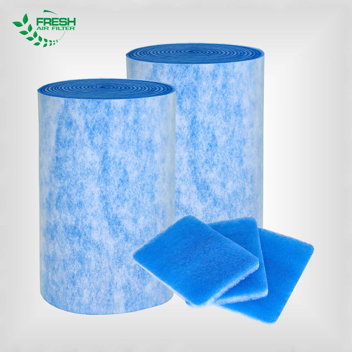
Synthetic fibers, primarily polyester and polypropylene blends, offer distinct advantages under aerodynamic stress. These materials provide excellent structural resilience under fluctuating face velocities. Synthetic fibers naturally resist moisture and do not break down or swell when subjected to humid, turbulent air. Manufacturers often apply electret treatments to these materials. This embedded static charge helps capture fine particles without tightening the physical weave, which would otherwise increase the initial pressure drop.
Field engineers specify synthetic pre-filter media for high-moisture or variable-flow environments. Composite or multi-layer synthetic designs utilize progressive density. The fibers are loosely packed on the air-entering side and become progressively denser toward the air-exiting side. This design handles high-velocity depth loading effectively. It distributes the dust cake throughout the entire depth of the media rather than forming a restrictive, solid layer on the surface. This prevents rapid blinding and extends the filter's operational life.
However, synthetic media has physical limitations. You will see sharp efficiency drop-offs if the media velocity exceeds design thresholds without proper pleat support. High velocities can strip the media's electrostatic charge over time. Once the charge dissipates, the mechanical efficiency of the loose synthetic weave drops significantly for sub-micron particles, allowing them to pass downstream.
Fiberglass remains a traditional choice for many legacy air handlers and heavy industrial applications. The thick, rigid nature of spun-glass fibers creates a highly open structure. This allows for excellent depth loading of large, dry particulates while keeping initial resistance very low, even at higher velocities.
You typically find fiberglass media in standard commercial HVAC units and industrial paint booths. Paint overspray capture relies heavily on the open weave of fiberglass to hold massive amounts of liquid or sticky particulate without immediately blinding the airflow. The progressive density of the glass fibers traps heavy paint droplets on the front and finer mist on the back.
Despite these benefits, fiberglass poses severe risks under high face velocities. The primary limitation is the risk of fiber shedding. High air speeds can physically snap the glass fibers, sending them downstream into the occupied space, ductwork, or sensitive manufacturing equipment. Additionally, fiberglass suffers from media compression. When velocity spikes, the aerodynamic pressure pushes the fibers together. This compression closes the air pathways, causing a sudden and severe spike in pressure drop. Structural failure and media blowout are common if face velocities exceed the manufacturer's rated limits.
Standard synthetic and fiberglass media melt, burn, or degrade rapidly in high-temperature environments. You must deploy specialized panels designed to maintain structural integrity under extreme thermal conditions. These units feature aluminized steel or heavy-duty galvanized frames. The media typically consists of micro-glass or woven ceramic fibers that withstand continuous high heat without off-gassing, melting, or structural collapse.
Install a heat resistant pre-filter panel in demanding applications like high-velocity industrial exhaust, oven processing, and heavy manufacturing environments. In these scenarios, both thermal stress and aerodynamic stress attack the filter simultaneously. The rigid panel construction prevents the media from fluttering, tearing, or bowing when subjected to high-velocity exhaust air. The specialized high-temperature binders used in these panels ensure the fibers remain intact even when temperatures fluctuate wildly during intense process cycles.
Media Type | Velocity Tolerance | Moisture Resistance | Primary Failure Mode at High Velocity |
|---|---|---|---|
Synthetic (Polyester/Polypropylene) | High (with pleat support) | Excellent | Loss of electrostatic charge, pleat bunching. |
Fiberglass / Spun-Glass | Low to Moderate | Poor | Fiber shedding, media compression, blowout. |
Heat Resistant Micro-Glass Panels | Very High | Moderate | Binder degradation if temperature limits are exceeded. |
Dust holding capacity determines exactly how long a filter can operate before reaching its terminal pressure drop and requiring replacement. High face velocities accelerate the formation of a dust cake. Fast-moving air packs the captured particles tightly against the media fibers. This alters the media's porosity and increases resistance rapidly over time. A loosely packed dust cake allows air to pass; a tightly packed cake acts as a solid wall.
You must evaluate depth-loading versus surface-loading media responses to velocity spikes. Surface-loading media traps particles entirely on the front face. Under high velocity, this surface blinds over almost instantly, killing airflow. Depth-loading media allows particles to penetrate the material. Multi-layer composite media provides superior high-velocity dust retention. The progressive density catches large particles early and fine particles deep within the media, preventing the restrictive surface cake and maximizing DHC.
Aerodynamic stress physically pushes against the filter structure with immense force. You must assess the risk of pleat bunching, media collapse, or bypass when face velocity exceeds the media's tensile limits. Pleat bunching occurs when air pressure forces adjacent pleats to fold into each other. This effectively cuts off the airflow to that section of the media, reducing the active surface area and spiking the pressure drop across the remaining open pleats.
Structural reinforcements are an absolute necessity for high-velocity applications. Manufacturers utilize welded wire backing to keep pleats rigid and evenly spaced. Rigid frames made of high-impact plastic, beverage board with cross-bracing, or metal prevent the entire filter from bowing or collapsing into the ductwork. If the frame bends, air bypasses the filter entirely, contaminating the downstream system with unfiltered air.
Fan energy represents the largest operational cost in any air handling system. Pushing air through restrictive media at high velocities requires massive electrical input from the fan motor. Specifying higher-grade pre-filtration media with a higher pleat count and lower initial resistance requires a larger upfront investment.
However, this initial investment offsets the fan energy costs associated with high face velocities. A filter that maintains a lower pressure drop over its lifespan allows the fan motor to run at lower speeds or draw less amperage. Over a standard operating cycle, the energy savings heavily outweigh the purchase price of structurally reinforced, low-resistance media. You stop paying the utility company to force air through a bottleneck.
Filtration stages do not operate in isolation. The pre-stage filter selection directly dictates the loading characteristics and operational lifespan of the main-stage filter. The pre-filter acts as the primary defense shield. If it fails to capture coarse particulate due to velocity blow-through, that heavy dust load transfers directly to the final filter. Final filters, such as HEPA or rigid cell units, are designed exclusively for fine particulate. Hitting them with coarse dust causes rapid blinding and catastrophic pressure spikes.
Managing different face velocities across stages requires precise engineering. Often, duct design forces high pre-stage velocities due to space constraints, while final filters require massive surface areas to slow the air down.
Measure the intake velocity at the pre-filter bank using a hot-wire anemometer. Pre-stage filters frequently operate at velocities between 25 and 65 cm/s to handle massive intake volumes.
Calculate the required media area for the main-stage filters. These require much lower velocities, typically 2 to 5 cm/s, to ensure diffusion mechanisms capture sub-micron particles effectively.
Install expansion plenums or v-bank final filter housings to slow the air down after the pre-filter stage.
Balance these ratios to optimize total system pressure drop and prevent aerodynamic bottlenecking at the final stage.
Proper specification directly impacts the facility's maintenance budget. A properly specified pre-filter operating at optimal velocity prevents premature blinding of the final stage. HEPA filters and high-efficiency final stages are expensive to purchase and labor-intensive to replace. By ensuring the pre-filter can handle the face velocity without shedding or bypassing, you protect the final stage. Extending a HEPA filter's life from one year to three years through optimized pre-filtration yields massive operational savings and reduces system downtime.
Blow-through occurs when high velocity forces previously captured particles to detach from the fibers and re-enter the airstream. This particle re-entrainment contaminates the clean side of the system. You will often see visible dust trails on the clean side of the filter housing when this happens. It occurs frequently when systems experience sudden startup surges or when media reaches maximum dust holding capacity.
To mitigate this risk, specify media with appropriate binder strength. The chemical binders hold the fibers together tightly, preventing them from separating under pressure. Additionally, utilize variable frequency drives (VFDs) on the fan motors. VFDs allow for a soft start, ramping up the airflow gradually rather than hitting the filter with a sudden, violent wall of air. This manages startup velocity spikes and protects the fragile dust cake.
VAV systems constantly adjust airflow based on building demand. This means the face velocity across the filter fluctuates continuously throughout the day. Media that relies heavily on electrostatic charge or loose fibers will exhibit unpredictable pressure drop curves as the velocity ramps up and down, making it impossible to schedule maintenance accurately.
Mitigate this by selecting synthetic media with a strictly linear resistance curve. You need predictable performance regardless of the fan speed. Furthermore, implement continuous differential pressure monitoring. Install digital manometers across the filter bank and tie them into the building management system (BMS). This provides real-time data, allowing you to track resistance changes and schedule maintenance before a velocity spike causes a structural failure.
Combining high heat with high velocity creates a worst-case scenario for standard filtration media. Synthetic fibers melt, and standard binders burn off, leading to total structural collapse. The fast-moving air accelerates the heat transfer, degrading the media faster than in static high-heat environments.
You must mandate the use of certified heat-resistant panels when operating temperatures exceed standard synthetic thresholds. Typically, any application exceeding 200°F (93°C) requires specialized media. Ensure the selected panel features mechanically fastened media packs rather than standard glue adhesives, as standard glues will fail under the combined thermal and aerodynamic stress, causing the media pack to blow out of the frame.
Install digital manometers across all pre-filter banks to track real-time differential pressure spikes and establish an accurate resistance curve.
Audit your current air handler face velocities using a hot-wire anemometer during peak fan operation to identify aerodynamic bottlenecks.
Replace standard flat panels with high-capacity pleated filters in systems exceeding 500 FPM to drastically reduce media velocity and fan energy draw.
Program Variable Frequency Drives (VFDs) with soft-start profiles to prevent sudden airflow surges from damaging the dust cake or causing blow-through.
Upgrade to mechanically fastened, high-temperature panels in any exhaust system operating continuously above 200°F.
A: Face velocity is the speed of air approaching the front opening of the filter housing. Media velocity is the actual speed of air passing through the filter material itself. You can lower media velocity by increasing the pleat count, which adds surface area, even if the face velocity remains high.
A: Pressure drop increases exponentially with face velocity. The relationship follows the physics formula where pressure drop is proportional to the square of the velocity. Doubling the face velocity will roughly quadruple the aerodynamic resistance across the filter, forcing the fan motor to work harder.
A: High face velocity reduces diffusion efficiency for sub-micron particles. The kinetic energy of fast-moving particles easily overcomes the electrostatic attraction of charged media, causing fine particles to blow straight through the filter rather than sticking to the fibers.
A: You should upgrade to specialized heat-resistant panels when continuous operating temperatures exceed 200°F (93°C). Standard synthetic media and adhesives will melt, degrade, or off-gas at these temperatures, leading to structural failure and blowout under aerodynamic stress.
A: Synthetic media performs exceptionally well in VAV systems because it resists moisture and maintains structural integrity during airflow fluctuations. You must select media with a linear resistance curve and proper wire pleat support to prevent bunching when air volumes spike.
A: Calculate face velocity by dividing the total airflow volume (in CFM) by the face area of the filter (in square feet). For example, 2,000 CFM passing through a 4-square-foot filter yields a face velocity of 500 feet per minute (FPM).
