


Views: 0 Author: Site Editor Publish Time: 2026-09-01 Origin: Site


High-efficiency air filtration dictates indoor air quality and system reliability. Deploying dense filter media without a staging strategy introduces severe static pressure penalties. These penalties degrade mechanical performance across the entire air handling unit. Facility managers and system engineers frequently face premature blower motor failure, frozen heat exchange coils, and spiked energy consumption. These operational failures stem directly from rapid filter loading in single-stage setups. Implementing a staged filtration sequence solves this mechanical problem. Utilizing progressively denser media distributes particulate loading and stabilizes airflow throughout the ductwork. This multi-tiered approach protects sensitive mechanical components while maintaining target air purity. We will cover how to map system architecture, select filter combinations, and balance pressure drops to optimize long-term mechanical performance. Proper staging prevents blower strain and keeps your coils clean.
Pressure Drop Management: Staged filtration intercepts large particulates early, preventing rapid pressure drop spikes across high-efficiency final filters.
Energy Efficiency: By stabilizing system loading, staged configurations prevent variable-speed drives (VFDs) from over-ramping and single-stage systems from starving for air.
Component Protection: A multi-tier approach extends the lifecycle of expensive final filters (like HEPA) and protects heat exchange coils from fouling.
System loading refers to the gradual accumulation of particulates within filter media. As dirt builds up, it forms a dust cake on the face of the filter. This cake physically blocks the microscopic pathways that allow air to pass through. The filter becomes more restrictive, and this increased resistance to airflow is measured as static pressure drop. Higher static pressure places direct mechanical strain on the HVAC blower motor. The motor must work significantly harder to push the same volume of air through the restricted media.
A successful filtration strategy must balance two competing factors. First, it must achieve the target MERV or HEPA rating required for the occupied space. Second, it must accomplish this without exceeding the maximum allowable static pressure of the air handling unit (AHU). When an HVAC air filter loads too quickly, it disrupts this delicate balance. The operating point on the fan curve shifts, leading to cascading mechanical failures across the entire system.
Understanding how different blower technologies react to the stress of filter loading helps in designing an effective staging strategy. Blowers are not universally adaptable. Their response to increased static pressure dictates how the rest of the HVAC system performs under load.
Single-stage systems operate at a fixed speed. They push a specific amount of air based on a clean filter baseline. As the filter loads and resistance increases, the volumetric airflow (CFM) drops proportionally. This reduction leads to poor temperature control and inadequate ventilation. More dangerously, low airflow across the evaporator coil prevents the system from absorbing enough heat from the return air. The refrigerant temperature drops below freezing, causing condensation on the coil to turn to ice. This ice further blocks airflow, eventually leading to a completely frozen coil and potential liquid slugging at the compressor.
Multi-speed systems attempt to compensate by stepping up output in rigid increments. They rely on relays to switch motor taps when a thermostat calls for more cooling or heating. While better than single-stage units, they lack granular control. They often overcompensate or undercompensate for dynamic filter loading. If a filter is partially loaded, the medium speed might not provide enough air, but the high speed might provide too much, causing noticeable temperature swings and drafts in the occupied space.
Variable Speed Systems (VFDs) automatically increase motor RPMs to overcome airflow resistance. They successfully maintain target CFM as the filter loads by constantly adjusting the frequency supplied to the motor. However, this automated compensation drastically drives up energy consumption. The fan affinity laws dictate that power consumption increases with the cube of the fan speed. If loading is not managed through staged filtration, the VFD will run at maximum capacity. This masks the airflow problem while pulling massive amounts of electricity.
Blower Type | Response to Filter Loading | Mechanical Risk | Energy Impact |
|---|---|---|---|
Single-Stage | Airflow (CFM) drops proportionally to resistance. | Frozen evaporator coils, compressor failure. | Low, but system fails to condition the space. |
Multi-Speed | Steps up to next rigid speed tap. | Short-cycling, uneven temperature distribution. | Moderate; operates inefficiently at wrong speeds. |
Variable Speed (VFD) | Increases RPM to maintain exact CFM setpoint. | Motor overheating if pushed beyond design limits. | High; exponential power draw at high RPMs. |
Designing a staged filtration system requires careful planning and a deep understanding of your specific air handling architecture. You cannot simply stack filters together and expect optimal results. Each stage must serve a distinct purpose, capturing specific particle sizes while maintaining acceptable pressure drops.
Before installing any new media, you must map the existing system. Create a comprehensive flow diagram of the air handling unit. Identify all outside air intakes, return air ducts, and mixing boxes. Locate the supply airflow measuring stations. This mapping process determines the optimal placement for each filter bank. It also highlights potential spatial constraints within the AHU housing.
You need to measure the physical track depth available in the unit. Standard commercial air handlers often ship with a simple two-inch track. Implementing a three-stage system requires significantly more space. You must verify that the fan motor has the horsepower to handle the combined initial pressure drop of multiple filter banks. Conduct a pitot tube traverse to establish baseline airflow and static pressure before making any modifications.
The first line of defense is the pre-filter stage. This stage typically utilizes low-resistance pleated filters, often rated around MERV 8. Their primary role is capturing lint, heavy dust, pollen, and large airborne debris. These filters are usually one to two inches thick and feature a wire-backed synthetic media.
Pre-filters absorb the bulk of the physical mass entering the system. By trapping these large particles early, they prevent the immediate fouling of secondary stages. This simple intervention dramatically extends the operational life of the downstream media. You should position pre-filters immediately after the mixing box, ensuring they catch both return air particulates and outside air contaminants before they reach the coils.
The intermediate stage captures mid-sized particulates that pass through the pre-filter. This stage requires media with high dust-holding capacity to prevent premature pressure drops. Standard pleated filters load too quickly in this position, restricting airflow and defeating the purpose of staging.
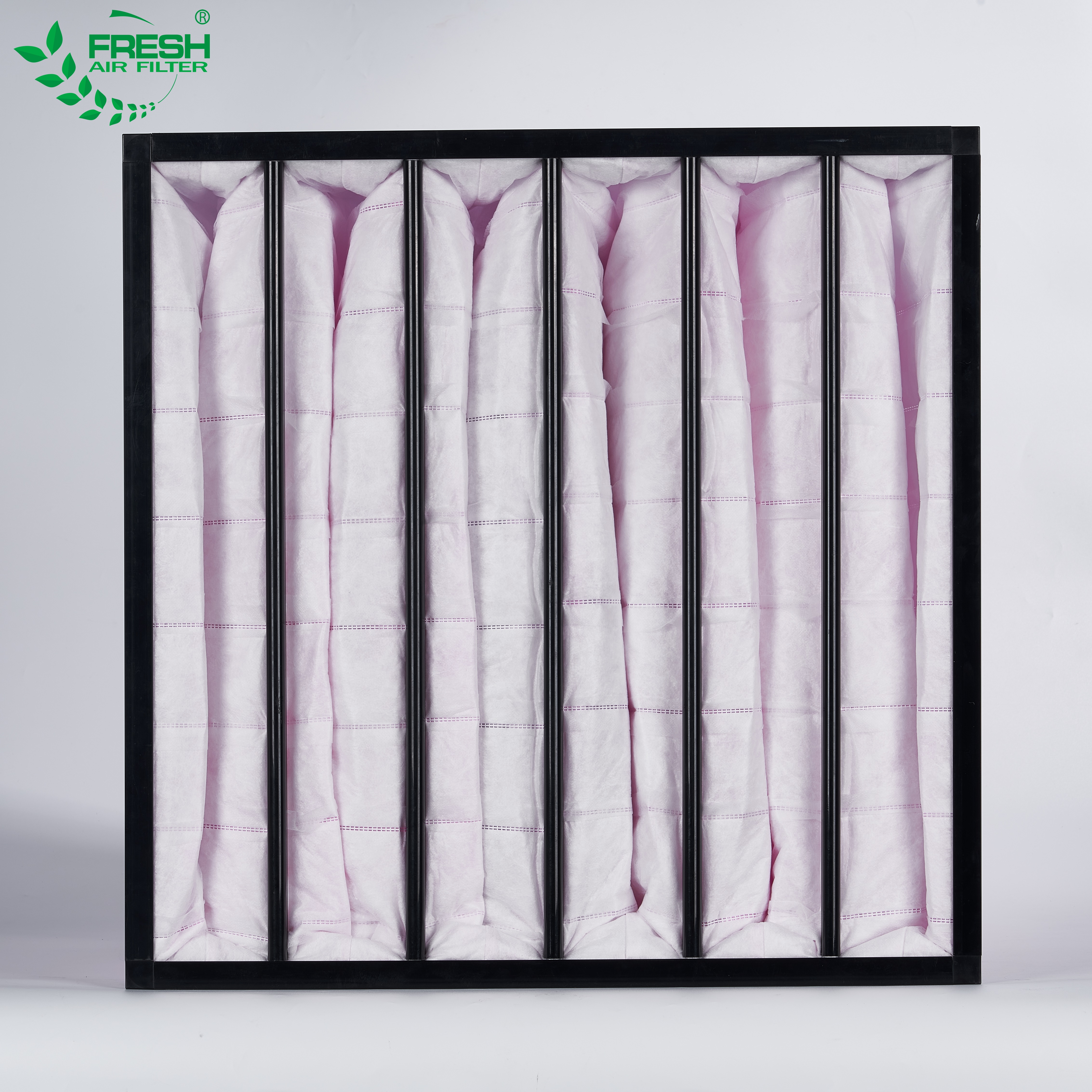
Integrating a pocket air filter for HVAC systems is highly effective here. Pocket filters feature deep, aerodynamic bags that inflate during operation. This geometry maximizes the available surface area. It allows the system to hold massive amounts of dust without disproportionately increasing static pressure. The bags can range from 12 to 36 inches in depth. You must ensure the filter housing has adequate clearance so the bags do not bottom out or rub against internal AHU components, which causes abrasion and media failure.
The final stage is reserved for critical environments like healthcare facilities, cleanrooms, and precision manufacturing floors. These applications require terminal filters capable of capturing sub-micron particles. This stage provides the actual air purity required by the facility specifications.
Deploying a mini pleat HEPA filter provides exceptional terminal filtration. The mini pleat design uses thermoplastic separators to maintain precise pleat spacing, packing maximum media into a compact frame. This creates a highly restrictive barrier that traps 99.97% of particles at 0.3 microns. However, this dense geometry relies entirely on upstream stages. Without proper pre-filtration, a HEPA filter will blind almost immediately. The microscopic pores clog with coarse dust, causing severe airflow restriction and requiring immediate replacement.
Staged filtration transforms how an HVAC system operates. It shifts the maintenance focus from reactive troubleshooting to proactive performance management. By controlling how and where dirt accumulates, you gain control over the mechanical behavior of the air handler.
The relationship between static pressure and energy consumption is governed by the fan affinity laws. These laws state that the power required by a fan motor is proportional to the cube of the shaft speed. Therefore, a marginal reduction in static pressure yields exponential energy savings. If you can reduce the required fan speed by just 10%, you reduce the power consumption by nearly 27%.
Pushing air through a single, heavily loaded high-MERV filter requires high RPMs and massive energy draw. The VFD ramps up to fight the localized restriction. In contrast, pushing air through a clean, staged array distributes the resistance across multiple media types. The overall operating pressure remains lower and more consistent. This stabilization keeps VFDs running in their most efficient frequency ranges, typically between 40 and 50 Hz, rather than maxing out at 60 Hz.
Staged filtration directly impacts control loops and the sequence of operations. Consistent airflow allows temperature and humidity sensors to provide accurate readings. When airflow fluctuates due to rapid filter loading, sensors register false loads, causing the system to short-cycle or hunt for the setpoint.
Integrating differential pressure sensors across each filter bank is highly recommended. You wire these transducers directly into the Building Management System (BMS) using standard 4-20mA or 0-10V signals. The BMS monitors the exact pressure drop across Stage 1, Stage 2, and Stage 3 independently. This integration allows you to automate maintenance alerts based on actual filter loading. You replace the pre-filter when it hits 0.5 inches of water column, rather than guessing based on calendar days.
Protecting heat exchange coils is a primary function of any filtration strategy. Staged filtration prevents micro-particulate bypass that eventually coats evaporator and condenser coils. Dirt acts as a powerful insulator on these aluminum fins and copper tubes, severely degrading thermal transfer efficiency.
Clean coils ensure sustained heat transfer and significantly reduced compressor runtimes. The system removes latent and sensible heat exactly as designed. Furthermore, preventing airflow restriction mitigates the leading cause of catastrophic HVAC failure. Low airflow mimics or exacerbates refrigerant charge imbalances. This condition causes the evaporator coil temperature to drop. Condensate freezes on the fins, completely blocking airflow, and eventually causing liquid refrigerant to flood back to the compressor, destroying the valves.
Staged filtration aligns perfectly with ASHRAE standards for commercial building maintenance. It provides a structured, predictable approach to system upkeep. You can plan maintenance shutdowns with precision because the BMS data tracks the exact loading curve of each filter stage.
Consider the difference in replacement schedules. In a single-stage high-efficiency setup, you must replace the primary filter frequently as it clogs with large debris. In a staged setup, you perform frequent pre-filter changes. This protects the intermediate and final filters, allowing them to remain in service for much longer periods. The labor shifts from difficult, heavy filter pulls to quick, lightweight pre-filter swaps.
Filter Stage | Primary Function | Typical Media Type | Expected Replacement Interval |
|---|---|---|---|
Stage 1 (Pre-Filter) | Capture coarse dust, lint, and pollen. | 2-inch Pleated (MERV 8) | 1 to 3 months |
Stage 2 (Intermediate) | Capture mid-size particles, high capacity. | Pocket/Bag Filter (MERV 11-14) | 6 to 12 months |
Stage 3 (Final) | Capture sub-micron particles, terminal purity. | Mini Pleat HEPA (99.97%) | 12 to 36 months |
While the mechanical benefits are substantial, implementing a staged filtration system requires navigating specific physical and operational challenges. You must engineer the solution to fit the existing infrastructure without creating new failure points.
The most common barrier to staging is physical space. Retrofitting older air handling units often reveals a lack of track depth for multiple filter banks. Standard AHUs may only have a two-inch track designed for a single pleated filter. Upgrading to a three-stage system requires structural modifications.
You may need to install custom filter housings or extend the mixing box to accommodate the deeper intermediate and final filters. If you are installing pocket filters, you must ensure there is enough downstream clearance so the bags fully inflate without hitting the chilled water coil. In tight mechanical rooms, extending the AHU casing requires custom sheet metal work and potentially relocating chilled water piping or electrical conduits.
System designers must balance initial and terminal pressure drops. Adding a pre-filter inherently increases the initial clean pressure drop of the system. You are placing more physical material in the airstream from day one. The blower must overcome the resistance of the pre-filter, the intermediate filter, and the HEPA filter simultaneously.
However, this initial penalty is a strategic trade-off. While the starting pressure is slightly higher, the pre-filter flattens the curve of the terminal pressure drop over time. The system avoids the extreme pressure spikes that occur when a single high-efficiency filter clogs with coarse debris. The average operating pressure over a six-month cycle remains lower and far more stable in a staged configuration.
The greatest risk in staged filtration is improper filter seating. Air behaves exactly like water; it always takes the path of least resistance. If dense filters are not seated perfectly flush against the holding frames, air will bypass the media entirely, shooting through gaps in the track.
This bypass introduces unfiltered air directly to the coils and the occupied space, defeating the purpose of the high-efficiency media. To mitigate this risk, you must upgrade to heavy-duty filter frames. Utilize proper closed-cell neoprene gasketing materials to create an airtight seal around every filter. Use P-clips or spring-loaded latches to compress the filter frame against the gasket. Finally, conduct regular differential pressure monitoring to verify that air is actually moving through the media, not around it.
Map your existing air handling unit to determine available track depth for multi-stage filter housings.
Install differential pressure transducers across each filter bank and wire them to your building management system.
Upgrade your primary filter tracks with heavy-duty closed-cell neoprene gaskets to eliminate air bypass.
Establish a baseline static pressure reading with clean media to set accurate alarm limits for future filter changes.
A: As media captures airborne dirt, the physical pathways for air shrink. This resistance forces the blower motor to work harder to maintain volumetric airflow. The increased effort raises the static pressure within the air handler. High static pressure alters control loop tuning, reduces overall airflow, and places severe mechanical strain on the blower assembly.
A: Pocket filters provide significantly more surface area than standard pleated filters. The deep bags inflate during operation, allowing for exceptionally high dust-holding capacity. This design maintains lower pressure drops during the intermediate filtration stage, preventing the blower from overworking while capturing mid-sized particulates.
A: Without pre-filtration, a HEPA filter rapidly clogs with large debris like lint and heavy dust. This causes severe airflow restriction and potential system failures like frozen evaporator coils. HEPA media is highly sensitive, and exposing it to coarse particulates destroys its lifespan and forces premature replacements.
A: Variable speed blowers automatically increase motor RPM to overcome the resistance of a loaded filter, maintaining airflow but exponentially increasing energy consumption. Multi-speed systems step up in rigid increments, causing temperature swings. Single-stage systems simply lose airflow entirely as resistance builds, leading to frozen coils.
A: A standard baseline involves replacing pre-filters every 1 to 3 months, intermediate filters every 6 to 12 months, and final HEPA filters every 12 to 36 months. Exact timing depends on pre-filter efficacy, outside air quality, and actual BMS differential pressure readings.
